D'Elete BC in NJ
Voyager  Dispensing gallons of useless information daily...
Posts: 1,671
|
Post by D'Elete BC in NJ on Mar 27, 2008 7:44:24 GMT -8
lol...d*mn, you are making me breakout the textbooks! ;D If you review my choice of words before, I said similar top speed, not same. Those words were chosen carefully!  I am using the definition of hull speed as the combination of the wave resistance limit (~30%), resistance due to the wetted surface(~30%), the form or block resistance (~10%), vortex generation off rudders and keels(~10%), and miscellaneous parasitic drag (~15%). I understand I was being simplistic before, but the argument I held to is technically correct. The two biggest effects determining the hull speed are the resistance induced by trying to climb over the pressure wave induced by the hull pushing through the water, which technically limits the maximum velocity to ~1.34 the SQRT of the waterline length, and the resistance of the wetted surface area. Now, you can push a vessel to a velocity in excess of 1.34 the SQRT of the waterline length, but as the vessel exceeds this velocity, the wavelength of the bow wave exceeds the length of the vessel, and it starts to drop into the trough of the wave, risking swamping if the wave is disturbed. In addition, the amount of resistance due to gravity increases dramatically as you begin to climb uphill instead of riding the two crests of the wave. This is relatively unchanged for a narrow vessel or a wide vessel of the same length. The wetted surface area friction is affected by both the laminar and turbulent components of the shearing force induced by the hull passing through the water. Yes, a wider vessel will have a larger friction component due to its larger wetted area, and possibly more turbulent flow (larger v SQ, and V CUBE components, as opposed to v components) but its influence is less pronounced as it is a percentage of a percentage, i.e. doubling the width of a ship may only increase the overall resistance by 15% as it only influences about 30% of the total resistance. I understand what you are saying about theoretical hull speed being a compromise of all the induced drags caused by moving said hull through the water and, to a lesser extent, the air, and the power available to reach the actual practical hull speed. This ought to be obvious from the more detailed description of hull resistance and the ultimate achievable hull speed I outlined above. My point before was, as I argued above, that changes in the width of the hull, much less the weight of the ship, have a much lower impact on the ultimate achievable hull speed than you were implying. I am of course ignoring other factors such as comfort and vessel fatigue, i.e. re your comment about cutting through the water as opposed to slamming through it, and the increased time to reach the designed hull speed needed if the mass of the ship is increased. |
|
|
|
Post by Northern Exploration on Mar 27, 2008 8:12:53 GMT -8
Can you review the parasitic drag calculations with me again. I have a few parasitic drags and would like to calculate how much they hold me back. None of them are family thank goodness cause they are harder to get rid of.  *sheesh. Engineers! As my younger cousin used to say in a plaintive voice to my grandfather (not the one you know Flug)," Papa, I just wanted an answer not a whole story." |
|
|
|
Post by oceaneer77 on Mar 27, 2008 16:50:46 GMT -8
doubling the width of a ship may only increase the overall resistance by 15% as it only influences about 30% of the total resistance.
..... I would love to get a copy of your text books.. As mine imply the reverse..
Are you looking into Reynolds numbers or Froudes law?..
At any rate Hull Speed is a non issue because it is a BS term.
Thanks Oceaneer77
|
|
|
|
Post by DENelson83 on Mar 27, 2008 16:59:25 GMT -8
I am using the definition of hull speed as the combination of the wave resistance limit (~30%), resistance due to the wetted surface(~30%), the form or block resistance (~10%), vortex generation off rudders and keels(~10%), and miscellaneous parasitic drag (~15%). And what about the remaining ~5%? |
|
|
|
Post by WettCoast on Mar 27, 2008 20:39:17 GMT -8
Double enders are common in the BC and WSF fleets where protected waters and relatively short hauls are the norm. But what about elsewhere in the world? Other than passenger only commuter ferries in places like New York and Sydney, Australia, I don't think they are very common. Perhaps someone can tell me otherwise. Also, are the Coast Boats not the first double enders ever built by FSG?
Are there any European ferry routes that use double ended ro-ro ships serving runs of 90 minutes and longer? Does the AMHS operate any double enders? So many questions...
|
|
D'Elete BC in NJ
Voyager
Dispensing gallons of useless information daily...
Posts: 1,671
|
Post by D'Elete BC in NJ on Mar 28, 2008 2:36:35 GMT -8
I am using the definition of hull speed as the combination of the wave resistance limit (~30%), resistance due to the wetted surface(~30%), the form or block resistance (~10%), vortex generation off rudders and keels(~10%), and miscellaneous parasitic drag (~15%). And what about the remaining ~5%? hmmm...hidden in the approximations... |
|
|
|
Post by kerryssi on Mar 28, 2008 8:06:50 GMT -8
For the non techies here you can eyeball a ship and tell if it is at hull speed. On a displacement hull when the bow wave comes up and the next wave comes up at the stern it it at hull speed. If the second wave is ahead of the stern it is not at hull speed.
Take a look at pictures of older sailboats. They have a long bow and stern overhang. This was to beat the rules in racing. The waterline length was set by the rules but with the long overhangs when the ship heeled over the waterline was extended and the ship went faster, with the same power.
The main problem with the fast cats was the 100 tons of weight added to the bow and stern by BCFC. No ship can perform as designed with that much extra weight. The idea behind the fast cats was to keep traffic flowing instead of moving it in large blocks. This would mean less infrastructure needed at each terminal and less strain on the road system. More sailings per day.
|
|
D'Elete BC in NJ
Voyager
Dispensing gallons of useless information daily...
Posts: 1,671
|
Post by D'Elete BC in NJ on Mar 28, 2008 8:34:34 GMT -8
.. As mine imply the reverse.. Could you explain what you mean here? You lost me.  You know what, let me answer that as I read the comment. If I understand what you are saying, you are stating that increasing the beam of a ship, i.e. increasing the cross-sectional area of the hull being pushed through the water, and the wetted surface area, you will see an increase in associated drag. Are you looking into Reynolds numbers or Froudes law?.. For a well-faired hull, an increase in width should not significantly affect the Reynold's number as it is based more on the length than the width of the object. Therefore, frictional resistance will increase in linear proportionality with the new hull area (basically, I know I'm glossing over several elements). Since Froude's formula is based around Reynold's, you are dealing with only the one dimensional change in the surface area...as this is a linear change, my statement holds true here, too. Now, let's look at the wave-making resistance...which is directly related to the prismatic/block coefficient and incorporates Froude's formula as a dimensionless number...if we assume we are going to only increase one dimension...i.e. beam...we are again speaking of a linear change in the total friction. Okay, go back to the my statement...looking deeper into my analysis, I'm a big boy, I'll admit I blew the increase in the wave resistance.  But, using the percentages I gave, which are lifted from data I researched out of a few papers, the total increase in resistance would still only be about 30-50% for a ship that is twice as wide with equivalent hull efficiencies. Definitely not as fast as the narrower ship given the same power-plant, but given ~50% more power and it would be. Plus, as an aside, the overall capacity of the vessel is increased significantly. At any rate Hull Speed is a non issue because it is a BS term. lol...BS as in Bachelor of Statistics? ;D That would be appropriate. Seriously though, I understand what you are saying...there are too many variables to rely on 1.34 the SQRT of the waterline length as the end all and be all of maximum hull speed. It is, however, a good statistical approximation for a efficient hull of typical dimensions. Would you prefer maximum attainable velocity for a given hull and power specification (mavfaghaps for short )? In that case, I'll shut up! ;D |
|
|
|
Post by Alex on Mar 28, 2008 23:05:51 GMT -8
man, I'm having flashbacks to my Fluid Dynamics class...
|
|
|
|
Post by doctorcad on Apr 8, 2008 9:30:11 GMT -8
How much trouble is it for the bridge crew to move from one end to the other?
Is it a 2 minute affair, or is there a complex handover that takes place?
|
|
D'Elete BC in NJ
Voyager
Dispensing gallons of useless information daily...
Posts: 1,671
|
Post by D'Elete BC in NJ on Apr 8, 2008 10:22:36 GMT -8
Okay, I remember something along these lines being discussed in another thread, complete with some photos of the bridge controls. I did a quick search with no luck. Anyone have a better memory than me?
|
|
|
|
Post by Dane on Apr 8, 2008 11:17:31 GMT -8
How much trouble is it for the bridge crew to move from one end to the other? Is it a 2 minute affair, or is there a complex handover that takes place? Reasonably simple, my memory may be flawed but: shut down most of the navigational controls, all crew but 1 move to the new forward bridge, actove nav control, 1 crew member in the arriving end bridge supervises loading/unloading and moves to the new bridge on departure. |
|
Quatchi
Voyager
Engineering Officer - CCG
Posts: 930
|
Post by Quatchi on Apr 8, 2008 12:02:34 GMT -8
I remember seeing a procedure manual PDF somewhere for transferring control from main console to a wing console on a Spirit. It was quite complex. Although didn't seem to take to long. I tried to find it but, couldn't.
Cheers,
|
|
|
|
Post by oceaneer7 on Apr 26, 2008 21:17:44 GMT -8
Hi BCNJ
Sorry for the long time to reply.. had to do another trip..
I agree totally with your last post especially magfaghaps!!
thanks for keeping me on my toes and making me find my books under all of the dust and $#8
Oceaneer77
|
|
|
|
Post by jimpilch on Apr 27, 2008 21:53:21 GMT -8
Transferring control from one station to another is a simple matter of putting the engine controls in the correct position and pushing a button. In the case of C class vessels, buttons in both wheelhouses have to be pushed at the same time to transfer control. After loading and prior to departure the Captain, in the now forward wheelhouse, pushes his transfer button and a designated person in the aft wheelhouse, pushes the other transfer button on the captains say so. Unless things have changed, that's how it worked originally.
|
|
D'Elete BC in NJ
Voyager
Dispensing gallons of useless information daily...
Posts: 1,671
|
Post by D'Elete BC in NJ on Apr 28, 2008 3:32:07 GMT -8
Hi BCNJ Sorry for the long time to reply.. had to do another trip.. I agree totally with your last post especially magfaghaps!! thanks for keeping me on my toes and making me find my books under all of the dust and $#8 Oceaneer77 lol...hey, same back...I've been sneezing ever since ;D... |
|
|
|
Post by doctorcad on May 2, 2008 10:25:50 GMT -8
Transferring control from one station to another is a simple matter of putting the engine controls in the correct position and pushing a button. In the case of C class vessels, buttons in both wheelhouses have to be pushed at the same time to transfer control. After loading and prior to departure the Captain, in the now forward wheelhouse, pushes his transfer button and a designated person in the aft wheelhouse, pushes the other transfer button on the captains say so. Unless things have changed, that's how it worked originally. Makes sense. Doesn't sound like too much of an encumberance. |
|
Neil
Voyager
Posts: 7,171
|
Post by Neil on May 13, 2008 11:04:52 GMT -8
Couldn't find a thread dealing just with fuel consumption, but since there's been some talk of that in this corner, I thought I'd post this old article from 1984 here... 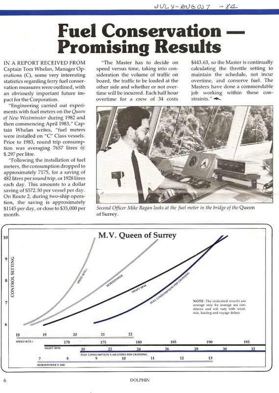 |
|
|
|
Post by Name Omitted on Dec 13, 2010 22:07:21 GMT -8
I've spent a lot of time on the Alaska Marine Highway, where we spend more time sailing than loading/unloading, so don't do much with double-enders, so here comes the 10 year old style stream of questions.
From a mechanical perspective, is there a true bow? Does the running crew migrate to one or the other bridge for long haul work? Below decks, is there one engine that drives shafts in either direction through a gear box? Is there a rudder on each side, and does the "bow" just lock into place, or is it used for steering as well? What sort of efficiency loss is there to such a design?
I assume Starboard and Port are relative to the ships current direction, and there are simply 2 sets of running lights, but inside the vessel, how are passenger signs notated (as in, which direction to the galley?)
|
|
|
|
Post by deepsea on Dec 13, 2010 22:29:16 GMT -8
Haha, no questions can ever be stupid on this forum, ever.
Yes, the bridge crew "migrate" over to the other end, prior to departure. And, generally, the double enders are run with 4 engines and there is a gear box which changes, the direction. So, all double enders generally run with 4 engines. Coastals can be run with just 3, if they are lightly loaded.
Both ends have bows, complete with a rudder at each ends. One end of the ship's prop will be "feathered", in mode 1. Mode 2 utilizes both props, to push and slow the ship, at the same time. In mode 2, both rudders are used, and in mode 1, I'm sure of it, just one rudder is used.
Interior signs are relative to which ends, the ship ties in. It's totally switchable, as recently the Inspiration switched sides. So, all they had to do was switch the signs too.
Coastals are so efficient at cruise, they can use 3 engines. So, the design of the hull is extremely efficient.
|
|
Nick
Voyager
Chief Engineer - Queen of Richmond
Posts: 2,078 
|
Post by Nick on Dec 13, 2010 22:51:31 GMT -8
Ok, I'll try to explain a little bit. Some of your questions would depend on the particular boat, so I'll address these as if you're speaking about a "mainline" double ender such as the Coastal Renaissance or Spokane, rather than a small double ender like the Mayne Queen.
From a mechanical perspective, both ends are identical. Generally, there are two modes of propulsion. Mode 1 is used under cruise and on course, and has all propulsion power sent to the aft propeller, and steering is done solely by the aft rudder. The bow rudder is locked into the 0 degree position, and the propeller is feathered to reduce drag as much as possible.
Mode 2 is used in maneuvering (docking etc) and has power provided to both the aft and forward propellers. The aft pushing the vessel ahead and the forward providing braking power. Also, both the aft and the forward rudders can be used to direct thrust. In this way the forward propeller and rudder behave almost like a bow thruster.
Machinery layout depends on the vessel. For example the C-class have one variable pitch propeller at each end driven by two MaK diesel engines, which are geared together with a system of clutches and gearboxes so that both engines can drive each or both propellers.
The Super-Cs or Coastals are different, in that they are diesel electric. Again, it has one variable pitch propeller at each end, but they are each driven by their own dedicated electric motor. Four diesel engines provide power to drive the electric motors. The Coastals are designed to be able to have maximum redundancy with respect to the diesels... ie they can make their design 21 kts on 3 engines, or 18 kts on 2.
All things being equal, a single ended vessel will be more efficient. Hulls with a defined bow and stern have lower drag, and also having a propeller and rudder at the bow increases drag significantly. However, a single screwed vessel is generally more efficient than a twin screwed ship, so there is an advantage there, considering most of the single ended ships we use are twin screwed for maneuverability.
Operationally, the crew will switch bridges when they switch directions. I'm not familiar with the handover sequence, so maybe someone else can chime in here. (Ferryman? Scott? Anybody?)
|
|
Quatchi
Voyager
Engineering Officer - CCG
Posts: 930
|
Post by Quatchi on Dec 13, 2010 23:14:25 GMT -8
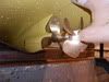
Well, nick did a fairly in depth job of explaining it, but he forgot to explain Controllable Pitch Propellers.
They are quite a simple concept, you change the pitch of the prop to provide better efficiency and faster control.
The pitch is the angle of the propeller blade relative to the shaft center-line. A propeller blade with no pitch is exactly perpendicular to the shaft and therefore produces no thrust at all. When you increase the angle to say 10 degrees from perpendicular you will produce thrust, change it more and you get more thrust. Producing more thrust requires more power, or the prop slows down. If you change the pitch to say -10 degrees you will produce reverse thrust and the prop will pull instead of push. Feathered means that the blades are positioned parallel to the shaft to decrease drag from them being pushed through the water while they are unpowered.
Generally, you get the most speed with the highest pitch and most power output from the engines (somewhere around 45 degrees is the most pitch you can have before you start to loose power). When youre running slow though you have more options, you can decrease the pitch on the props to decrease thrust, this decreases the load on the engines as well, but they are still turning about the same speed. You can then decrease the speed of the engines and increase the pitch a bit to get the same thrust, but a more efficient running system. It is a balancing act of pitch and power from engines to get the most efficient combination when not running at full power, it also allows you to more accurately find the most efficient way to power the ship and produce the most speed with the least amount of fuel.
CPP also allows for very quick changes in thrust direction for maneuvering as well as providing for better low end control of thrust power. It also mean you don't need engineers on standby all the time waiting to change the engine speed as the bridge can make minor speed adjustments with the props instead of telegraphing for every change in speed they need.
Cheers,
|
|
|
|
Post by Low Light Mike on Dec 14, 2010 7:00:41 GMT -8
I assume Starboard and Port are relative to the ships current direction, and there are simply 2 sets of running lights, but inside the vessel, how are passenger signs notated (as in, which direction to the galley?) For lights: each corner has a light that can be shown as either red or green. For interior signs for the passengers: - the ever-dependable arrow system works. Just follow the arrow for the direction to any of the listed amenities. Nothing is listed as forward or aft for the passengers. Arrows to point the way, and some silly colour-code and animal-code signs to help people find their way back to their cars (I'm in the "dolphin section" of the car-deck ;D ). ...and any type of well-articulated question is always welcome here! |
|
Kam
Voyager
Posts: 926
|
Post by Kam on Dec 14, 2010 9:01:34 GMT -8
Here is a video showing a CPP in operation:
|
|
|
|
Post by Name Omitted on Dec 14, 2010 9:37:09 GMT -8
Thank you all very much.
Has there been any discussion about experimenting with mermaid pods or Voith Schneider propellers?
|
|


 I am using the definition of hull speed as the combination of the wave resistance limit (~30%), resistance due to the wetted surface(~30%), the form or block resistance (~10%), vortex generation off rudders and keels(~10%), and miscellaneous parasitic drag (~15%).


 You know what, let me answer that as I read the comment. If I understand what you are saying, you are stating that increasing the beam of a ship, i.e. increasing the cross-sectional area of the hull being pushed through the water, and the wetted surface area, you will see an increase in associated drag.
 But, using the percentages I gave, which are lifted from data I researched out of a few papers, the total increase in resistance would still only be about 30-50% for a ship that is twice as wide with equivalent hull efficiencies. Definitely not as fast as the narrower ship given the same power-plant, but given ~50% more power and it would be. Plus, as an aside, the overall capacity of the vessel is increased significantly.